An application of continued fractions to composite electrical resistor design

I was teaching Ohms laws law and introductory circuit calculations bout two days ago at a Swedish gymnasium, a subject  which I’m about as adept as now as I was when I myself took the class 7 or so years ago. There are basically only two formulas one has to learn in that course and those are the two effective resistance formulas for resistors in series and resistors in paralell

R = R_1 + R_2 + ... + R_n, \qquad \cfrac{1}{R} = \cfrac{1}{R_1} + \cfrac{1}{R_2} + ... + \cfrac{1}{R_m}

Not sufficient to describe circuits with more complicated  typologies such as bridges like the Wheatstone bridge but sufficient for at least engaging in some basic design.

The problem which came to mind as I was reviewing the material was how one would set out to build a circuit element with a specified resistance from a given set of elements. Usually it’s the other way around. You get the component and  you compute the resistance but the inverse problem of getting a specified resistance and then designing the circuit from some pieces if of course a lot more interesting and as we shall see in this special case surprisingly straightforward.

Let us study this particular problem: “Given a set of resistors with resistance R how does one combine these to form an element with a specified fractional resistance \cfrac{p}{q}R“. If we want an integer multiple or integer fraction or a specific resistance then things are straightforward, just chain p together to get a resistance pR or put q in parallell to R/q and this is the smallest number of equal number of components you need. seriesnadparalellresistors.png

For fractional resistances of a more general form however there are clearly very different ways you can go about designing the circuit and there are different benefits to them

Solution one: Construct $latex $q$ chains with p resistors each and put those chains in parallel

mWastefulResistor1.png
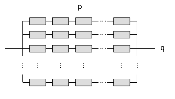
The chains have resistance p R and putting $latex $q$ of them in paralell reduces the total resistance by a qth to p R / q.

Solution two: Another is to first create p blocks of $latex $ resistors in paralell and then put those in series.paralellfirstthenseries.pngHowever both of these solution has the disadvantage that it requires  a total number of pq resistors to complete it which for most fractions becomes very impractical.

My question was therefore if there was a simple way to get a component with this resistance but which wouldn’t require quite so many resistors. Let us just start off by making clear that it is possible. These two components you see below both have the same resistance 2R/3

correctedthingresistor.png

but the right one was built using only 3 resistors instead of 6 which is (if you count by means of manufacturing cost) is a more effective solution. And the process or computing the resistance of the latter composition betrays the coming idea

\cfrac{2}{3} = \cfrac{1}{1 + \frac{1}{2}}

(I will henceforth just set R = 1) Usually one would have used ^(-1)-notation for the parallell coupling but not doing that reveals the continued fraction expression associated with this construction.

The central idea can be laid out as follows inductively. If you want to design a component with resistance $p/q$ (where p/q is a reduced fraction such that p < q) perform euclidean division and rearrange it according to

1

\cfrac{p}{q} = \cfrac{p}{dp + r} = \cfrac{1}{d + \cfrac{r}{p}} = \cfrac{1}{\cfrac{1}{1/d} + \cfrac{1}{p/r}}

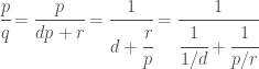
We now recognize the right hand side as the expression for the resistance of two resistor with resistance 1/d and p/r in parallel. The idea can diagrammaticaly be represented by

chaining.png

The 1/d resistor is constructed by putting d resistors in parallel and the p/r resistor is constructed by repeating the induction step.**

This can be streamlined by first computing the continued fraction of a fraction and then move backwards to form these construction steps . Take for example the continued fraction for 7/24

\cfrac{7}{24} = \cfrac{1}{3 + \cfrac{1}{2 + \cfrac{1}{3}}}= [0; 3,2,3]

which now contains a recipe for designing the composite resistor

corrected724resistor.png

Where the top 3-parallell component corresponds to [0;3,2,3], the 2-series at the bottom to [0;3,2,3], and the 3 in series at the bottom to [0;3,2,3].

Not all continued fractions will however have so small numbers in the expansion and especially when the numerator and denominator are fibonnacci numbers we’ll still end up with having to use a very large number of resistors.

What is kind of nice though is that irrational numbers which have a quickly convergent continued fraction can be approximated pretty accurately. \pi for example has a continued fraction [3;7,15,1,292,1,1,…] which means you can use the approximation \pi \approx [3;7,15,1] = [3;7,16] which using only 26 resistors gives 6 digits of pi which is pretty neat. A

PiInAcircuit.png

I’ve got half a mind to build this circuit to see if it checks out but unfortunately cheap hobby resistors only have about 1% accuracy to them so you’d only really end up with 3 digits tops.

EDIT: Many of the diagrams in the original publications had errors in them which made them not agree with the text and which were corrected around one hour later.

Magnet assisted one way crank

This evening I took a trip by the Museum of Technology in Stockholm. Its somewhat recently undergone a redesign since last I was there maybe 7 years ago and I was interested in seeing how its turned out. General judgement is that it is now absolute heaven for families with small children with lots of novel contraptions and controller less video games while there is a little less on offer with respect to showcasing historical mechanism but still a fair trade.

I had gone primarily to get some stimulus and inspiration for mechanical configurations and mechanism which are simple enough to turn into elementary physics problems but which aren’t completely disjointed from applications. Like the hand crank wheel turning mechanism on a quaint car-like thing where the crank moves a rack back and forth which is linked to an elongated arm connected to the wheel joint.

20160302_184725.jpg

The principal novelty however which I would like to point to a little was one I found in a machine that wasn’t even working. It was another crank mechanism where by turning a crank you set in motion a sequence of chains and gears which lifted some balls up to some slides of different curvature illustrating the principles of Brachistochrone problem. Everything about this machine was delightfully improvised which is why the electronics had broken down rendering the thing inoperable but what I want to talk about instead is a curious element in the crank mechanism.

20160302_191026.jpg

It is admittedly hard to make out in this image but the odd parts were the two rubber elements which are in contact with eachither in the middle.

When the crank is pushed forward nothing of note happens. The whole axis, rubber parts and all, move together, turn the chains and everything works.

It is when you try to push the crank in the reverse direction that something novel happened. Since the machine isn’t supposed to be run in reverse reasonably there are two possible things that might happen, either there is a ratchet somewhere which prevent reverse motion entirely or you put in something similar to a freewheel that the crank becomes disengaged and you move it backwards with zero resistance.

Neither of those things happened here however. Now at first if you pulled it in the reverse there is a full stop, seemingly there is a rachet somewhere down the line, however if you try to turn the crank back harder the right rubber element somewhat dramatically begins to slip and you can turn back the crank almost freely.

path13437-3-9-9-3.png

This feels really really weird when this happens but also oddly familiar. A snapping you shouldn’t encounter in a purely mechanical system. The reason for how these rubber elements stuck together when the torque of the crank was low such as in the forward motion and the gentle reversed motion is that they weren’t sticking together by friction at all. There was pair of magnets embedded in the rubber keeping them together.

20160302_191020.jpg

When the torque on these rubber elements becomes too high the magnets are pulled apart and the crank can move backward freely.

path1565.png

This was just so bafflingly weird this must have been an improvised fix to some problem they realized too late was present in the overall design. My guess is that the problem is that the ratchet preventing backwards motion of the system (not explicitly the crank) is located too far way from the crank somewhere down the line in a way that the reverse torque puts strain on something in the fixture, wood or plastic, which risks breaking if pulled back too hard. This is for children after all and if they can break it they will. The magnets guarantee that the torque on the axis has a manageable maximum at which the magnetic link snaps instead of something else in the machine..